| |
 |
|
| |
Mini-MCA
Tetracam's
Miniature
Multiple Camera Array
Note: This
product is no longer in production. It has been replaced by
the Macaw and the Micro-MCA.
|
|
|
|
|
|
|
|
|
|
| |
Mini-MCA Image Size
The image that is captured on each Mini-MCA sensor
and stored in each camera's flash memory is made up of 1280 x 1024
pixels (1.3 MPel). Each pixel contains 8 or 10 bits of data
depending upon the file format selected by the user (i.e., 10 bit DCM
lossless, 8 bit RAW, and 10 bit RAW file types).
In total, with each exposure the Mini-MCA4 captures
5.2 Megapixels (4 X 1.3 MPel) of image data on four separate sensors
and passes this to four separate flash memory cards. Each card stores a
separate band of radiation. The Mini-MCA6 captures 7.8
Megapixels (6 X 1.3 MPel) of image data and passes
this to six separate flash memory cards. The
Mini-MCA12 captures 15.6 Megapixels (12 X 1.3 MPel) of image
data and passes this to twelve separate flash memory cards.
Since each image is
stored with metadata that identifies ancillary information such as the
GPS coordinates where the image was captured, the Mini-MCA's standard
four, six or twelve 2GB cards are able to typically store approximately
500 to 900 images per channel. Higher image counts are
possible when larger compact flash memory cards are inserted into the
Mini-MCA in place of the 2GB cards included with the system..
PixelWrench2,
the software also included with the system, enables merging, viewing
and analysis of the images captured at each exposure and conversion of
the camera's native file formats into more common formats such as BMP,
JPEG, TIFF, PNG, etc.
|
|
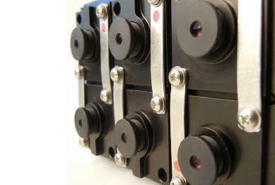
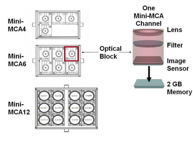
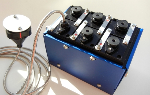
The Mini-MCA is a lightweight, compact version of
Tetracam's MCA (Multiple Camera Array) system which it
replaced. Like the MCA, Mini-MCAs are available in three
models. These are identified as the Mini-MCA4, Mini-MCA6 and
Mini-MCA12. The number in the model name identifies the
number of cameras in the array.
Each Mini-MCA system contains 4, 6 or 12
factory-aligned multi-spectral cameras. Each camera contains
a customer-specified narrow-band filter that is inserted between the
lens and sensor. With each exposure, 4, 6 or 12 separate bands
of visible or near-infrared radiation move through each camera's lens
and filter to form a separate monochromatic image on the camera's
sensor. The images from each camera in the array are
simultaneously transferred to each camera's compact flash memory card
for later access by the user.
Analysis of the combination of multi-spectral
images captured during each exposure enables Mini-MCA users to identify
plant stress factors, soil types, fertilizers, or insecticides;
differentiate plant species or recognize other plant, soil or chemical
conditions that are, in each case, able to be identified by their
unique spectral signature. Mini-MCA systems are also used to
graphically illustrate vegetation indices such as NDVI that are defined
by relationships of specific narrow-band wavelengths.
Additional information about observed vegetation may be derived from
these.
|
|
| |
Mini-MCA Sensitivity and
Filter Selection
Each Mini-MCA
channel may be equipped with a specific narrow-band filter which in
combination with other user-selectable filters on the
system's other channels enables the Mini-MCA to expose a
particular condition or enable the user to perform a particular
function. And, because Mini-MCA filters may be replaced by
users in the field, these systems may be re-purposed again and again to
detect different wavelengths at different times for different purposes.
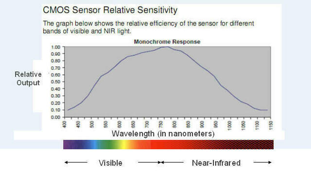
The camera's image
sensor's output is optimized for receipt of wavelengths at
approximately 800nm dropping in a smooth curve to 20% peak output at
450 nm in the visible spectrum and 1050 nm in the near-infrared
at the limits of its range. A
graph of the sensitivity of the camera's image sensor to impinging
radiation is shown below.
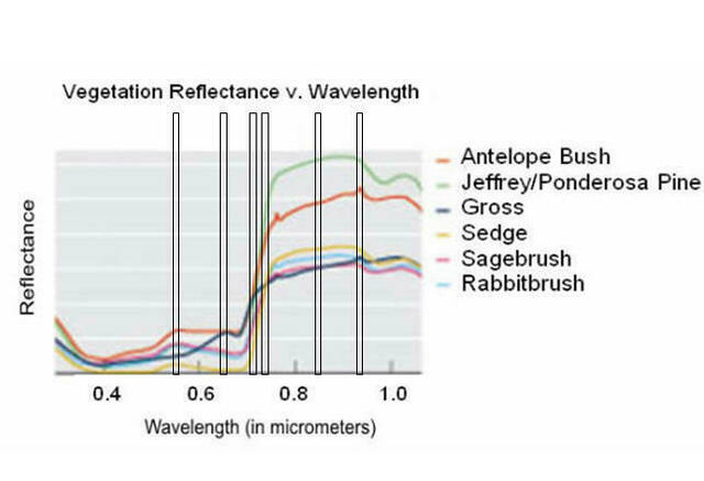
By choosing a specific narrow band optical filter
that is within the sensor's range to place in front of each channel's
sensor, the radiation that is able to reach each sensor may be
restricted to a specific narrow band of wavelengths. In this
way, specific filter combinations may be selected that allow the
Mini-MCA to expose a variety of plant conditions identifiable by their
unique spectral signature. For example, if the spectral
response of various plants are known in the region of the spectrum
monitored by the Mini-MCA, filters may be selected that will help
differentiate one species from another (see graphic below).
This, of course, requires that the user knows which filters to select
in advance in order to expose the sought-after differences.
Note: For an excellent resource on spectral signatures of
vegetation, reference "Hyperspectral Remote Sensing of Vegetation"
by Dr. Prasad Thenkabail, et al. available from
Tetracam or our Multispectral
Crop and Application Database.
Alternatively, the Mini-MCA may be set up to
monitor specific bands of wavelengths from which vegetation indices may
be extracted.
These
provide information needed for extraction of NDVI, SAVI and other
indices as well as information that is able to be deduced from these.
The band pass filters
provided with the unit are customer designated at the time of order.
These may be easily changed in the field in order to re-configure the
system to look for different spectra to expose different
conditions. Standard filters (shown below) are included in
the price of each system. Alternative special or custom band
pass filters are available upon request with prices provided via a
quotation. Additional information regarding band pass filter
selection is available
here.
|
|
| |
Mini-MCA
(with 9.6 mm Lens)
Ground Resolution & FOV Examples
The Mini-MCA's field of view (FOV) is laid out in a
4:3 format. The horizontal angle of view for each Mini-MCA
camera is 38.26 degrees. The vertical angle of view is 30.97
degrees. When carried in a manned or unmanned aircraft, the
field of view of each camera increases as the system's above ground
level (AGL) altitude increases. As the altitude increases, each
camera's ability to resolve individual details on the ground
decreases. When flown at altitude of 400 feet above
ground level, each Mini-MCA channel creates an image large enough to
capture nearly one and one-half acres at a resolution of approximately
two and a half inches per pixel in a single
shot. See chart below for example ground
resolution and FOV when the camera is flown at various
altitudes. PixelWrench2 contains a FOV Optical Calculator for
determining FOV and ground resolution at an altitude,
|
Sensor & Lens Parameters
|
Object
Distance
(Altitude
Above Ground Level in meters)
|
Ground
Resolution
in
mm per pixel
|
FOV
(width
x height)
in
meters
|
|
The values shown at right were derived from the FOV
(Field of View) Optical Calculator contained in Tetracam's PixelWrench2
software (included with all Mini-MCA cameras) using the current values
for the Mini-MCA camera shown below:
Sensor Dimensions (mm): 6.66 x 5.32
Pixel Size (microns): 5.2
Camera Lens Focal Length (mm): 9.6
|
122
m (~ 400 ft)
|
66
|
84
x 67
|
|
213.4
m (~ 700 ft)
|
116
|
148
x 118
|
|
365.8
m (~ 1200 ft)
|
198
|
254
x 203
|
|
915
m (~ 3000 ft)
|
496
|
635
x 508
|
Note: In order to view a
larger composite image of an area of interest, users may purchase third
party software that stitches multi-spectral images of adjacent areas
captured by a Tetracam system together into a larger image
mosaic. For information on such software, please send us email.
System Controls and
Connections
|

|
|
Mini-MCA System Menu
User control of the Mini-MCA is accomplished
through hierarchical system menus such as the one shown at right. These
are accessible by means of an external ADC/MCA Controller box and
visible via an interconnected video display (supplied by the
user). The system menus may also be access via the system
software (PixelWrench2) running on a Windows computer connected to the
Mini-MCA through its USB interface. The system menus present users with
a series of configuration choices. Scrolling through and
selecting these configures the camera. Check out the User
Manual (viewable via the link below) for precise descriptions of the
system menus.
|
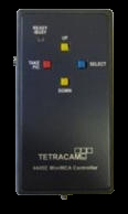
| ADC/MCA Controller Box
The ADC/MCA Controller Box (shown at right) is
included with each Mini-MCA system. This contains buttons that enable
the user to manually scroll up and down through system menus, pick a
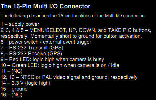
selection or take a picture. Via its 16-Pin Multi-I/O connector, this
box also may be used to interconnect the Mini-MCA with the RS232
transmit and receive lines of an optional GPS receiver in order to
determine GPS coordinates at image capture time. The box may also be
used to interconnect the Mini-MCA's NTSC or PAL video signal output to
an external monitor in a manned aircraft or to a video transmitter in a
UAV
|
|
 |
|
USB
Connection for Accessing System Via Computer
Mini-MCA
image systems feature a fast USB interface (located behind the access
panel on the Mini-MCA which also provides access to the system's
compact flash memory cards). The provided USB cable interconnects
Windows-based computers to the camera through the USB link.
If the camera is set via its menu settings to
USBMODE = DISK, then the computer may transfer images and exchange data
with the camera via this connector (but not trigger the camera to
capture images). If the camera is set via its menu settings
to USBMODE = CAMERA, then the USB connector may be used to trigger the
camera from, for example, an on-board laptop running Windows
and
SensorLink.
PixelWrench2 software supplied with the camera provides full camera
control as well as image management and analysis via the camera's USB
connection.
|
 |
|
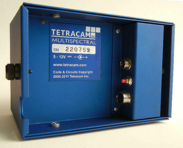
Back Panel Connectors
& Controls
Power
– 12VDC center positive supply capable of delivering 1.0 Amps
continuous. The supplied wall-plug type supply connects to this jack.
The camera is also supplied with an un-terminated power cord. In a
manned or unmanned aircraft, 12 VDC may be supplied by the craft via
this cable or through the Multi-I/O cable.
Camera
Trigger - Red button that when pushed triggers camera to capture
image. The Mini-MCA may also be triggered in a variety of
other ways - see below.
Multi-IO Circular
Connector - Information on the Mini-MCA's circular Multi-IO connector
and the cables that that are available from Tetracam to connect to it
are shown on our web site here.
Check
out the User Manual below for
precise descriptions of all of the Mini-MCA controls and
connections.
|
Camera
Triggering Options
The Mini-MCA cameras are synchronized to trigger at
the same time through various means depending upon the user's
preference. These include:
-
On-Camera Shutter
Release: The Mini-MCA possesses a red trigger button on the camera
itself which when pressed triggers the camera
-
Auto-Timer: The
Mini-MCA may be configured to capture images continuously at intervals
specified by the user via the camera's system menus. Press the Shutter Release or
trigger the system via one of the methods below to begin continuously
capturing images. Press the Shutter Release or trigger the
camera again to stop continuous capture of images. Always
stop continuously capturing images by pressing the On-Camera Shutter
Release or via a trigger command prior to powering the system
off. Interruption of power during continuous capture of
images may damage the Mini-MCA.
-
Remote Shutter Release: The Mini-MCA's included
ADC/MCA Controller Box enables users to manually trigger the camera by
pushing a button at the desired moment. This is the commonly-used
method of pilots aboard manned aircraft.
-
Computer Triggering: The camera may be
triggered through its USB interface. Optional GetShot
software enables remote triggering under command of a linked computer. Optional SensorLink
GPS waypoint
triggering application enables camera triggering at pre-defined
waypoints, a popular method used in manned aircraft.
-
External Triggering on UAV: Used on a UAV, UAV
circuitry may be patched into the ADC/MCA box in order to deliver a
low-true TAKE PIC command to the camera via Pin 5 on the Multi-I/O
connector.
-
RS-232 Triggering: The camera may be
commanded to trigger by receiving an <ESC> T command via
the RS232 connection on the ADC/MCA Box. Due to the delays
incumbent in a serial interface, the RS232 link is more commonly used
to transfer GPS position coordinates to the camera at camera trigger
time. When the camera is connected to a GPS receiver via an RS232 link
to the ADC/MCA box, the camera records the coordinates of the location
at which each image is captured into its log file upon receiving any
camera trigger command.
|
Standard System Contents
| |
MINI-MCA4 STANDARD SYSTEM ** |
|
MINI-MCA6 STANDARD SYSTEM ** |
|
MINI-MCA12 STANDARD SYSTEM ** |
| |
|
|
|
|
|
| |
The Mini-MCA4 System
Includes:
4 channel Mini MCA camera
4 ea. 2 GB Certified CF Cards
4 ea. 9.6 mm lenses
4 ea. 1.3 MB image
sensors (5.2 MB total)
4 ea. Standard Bandpass Filter Set *
- 490FS10-25
- 550FS10-25
- 680FS10-25
- 800FS10-25
Plus
one each of the following:
ADC/MCA
controller box & 6' Multi-I/O cable
12 VDC external power supply
System CD with PixelWrench2 software (PW2)
(See additional System CD contents under Features below)
Rugged Pelican Carrying Case
USB Cable
Power Cord (un-terminated on one end)
White Teflon Calibration Plate (AKA Calibration tag or Software
Calibration Tile)
|
|
The
Mini-MCA6 System Includes:
6 channel Mini MCA camera
6 ea. 2 GB Certified CF Cards
6 ea. 9.6 mm lenses
6 ea. 1.3 MB image sensors (7.8 MB total)
6 ea. Standard Bandpass Filter Set *
- 490FS10-25
- 550FS10-25
- 680FS10-25
- 720FS10-25
- 800FS10-25
- 900FS20-25
Plus
one each of the following:
ADC/MCA
controller box & 6' Multi-I/O cable
12 VDC external power supply
System CD with PixelWrench2 software (PW2)
(See additional System CD contents under Features below)
Rugged Pelican Carrying Case
USB Cable
Power Cord (un-terminated on one end)
White Teflon Calibration Plate (AKA Calibration tag or Software
Calibration Tile)
|
|
The
Mini-MCA12 System Includes:
12 channel Mini MCA
camera
12 ea. 2 GB Certified CF Cards
12 ea. 9.6 mm lenses
12 ea. 1.3 MB image sensors (15.6 MB total)
12 ea. Bandpass Filter Set *
- 490FS10-25
- 520FS10-25
- 550FS10-25
- 570FS10-25
- 671FS10-25
- 680FS10-25
- 700FS10-25
- 720FS10-25
- 800FS10-25
- 840FS10-25
- 900FS20-25
- 950FS40-25
Plus one each of the following:
ADC/MCA controller box & 6' Multi-I/O cable
12 VDC external power supply
System CD with PixelWrench2 software (PW2)
(See additional System CD contents under Features below)
Rugged Pelican Carrying Case
USB Cable
Power Cord (un-terminated on one end)
White Teflon Calibration Plate (AKA Calibration tag or Software
Calibration Tile)
|
|
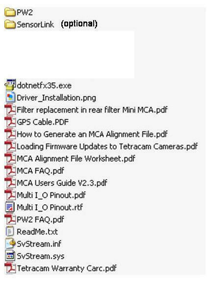
Mini MCA System CD Contents
List of files on included System CD:
|
Option Notes:
* Alternative band pass filters
available upon request with quotation. Additional information
regarding band pass filter selection is available
here.
Each Mini-MCA is a modular system that allows the
end user to combine and sync multiple cameras together. Individual
optical blocks may be removed from a Mini-MCA4, 6 or 12 to provide a
lesser number of channels, if desired.
Systems are provided with 2 GB compact flash
memories (larger storage is available via quotation)
Other Options Commonly Purchased with this Product:
** For Mini-MCA Master Camera only
Typical Availability: 3 to 4 weeks - Faster
turn-around times are often possible so please contact us to
confirm availability or to obtain more information regarding
configuration options and pricing.
|
 |
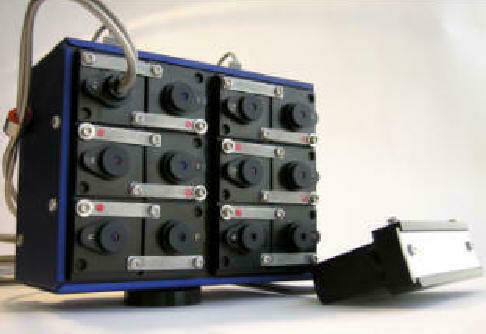 |
| Mini-MCA6 Equipped
with Incident Light Sensor |
Mini-MCA12
Equipped with Incident Light Sensor |
Summary
of Mini-MCA System Features and Specifications
|
|
Specification/Feature
|
|
Description/Value
|
|
Remarks
|
|
|
|
System Overview
|
|
5.2
to 15.6 MPel Configurable Camera Array of 4, 6 or 12 Multispectral
channels (~450 to ~ 1000 nm) for Manned and Unmanned Aircraft
|
|
|
|
|
|
Sub-Models/Part Numbers
|
|
Mini-MCA 4 /
TTC1024-Mini MCA 4
Mini-MCA 6 /
TTC1021-Mini MCA 6
Mini-MCA12 /
TTC1025-Mini MCA 12
|
|
|
|
|
|
Default Ports (one each of the
following ports)
|
|
USB
1.1 data connection, RS232 Serial, Video (NTSC or Pal), Remote Shutter
(External Trigger)
|
|
|
|
|
|
Image Triggering
|
|
On-Camera
Shutter Release, Auto-Timer, Remote Shutter (External
Trigger), Computer Trigger via USB, RS232 Serial Trigger
|
|
|
|
|
|
|
|
|
|
|
|
|
|
Power
|
|
|
|
|
|
| |
Voltage Input
|
|
+ 9 VDC to + 14 VDC Center Positive
|
|
|
|
|
|
Nominal Current Draw
|
|
Mini-MCA4
- 300 milliamps
Mini-MCA6
- 450 milliamps
Mini-MCA12 - 900
milliamps
|
|
|
|
|
|
Typical Power Consumption
|
|
Mini-MCA4
- 4 Watts
Mini-MCA6
- 5.4 Watts
Mini-MCA12 - 9 Watts
|
|
|
|
|
|
|
|
|
|
|
|
|
|
Mini-MCA Sensor
|
|
|
|
|
|
|
|
Range
|
|
~450 nm to ~ 1000 nm
|
|
|
|
|
|
Dimensions
|
|
6.66 mm x 5.32 mm
|
|
|
|
|
|
Pixel Size
|
|
5.2
microns
|
|
|
|
|
|
Filters
|
|
Each system holds 4, 6,
or 12 user-selectable field-changeable 25 mm standard narrowband
spectrometer filters (1 per channel in bandwidth increments > 1
nm). Typical bandwidth increments equal 10 nm.
|
|
Mini-MCA filters are customer designated at the time of
order. These filters may be replaced by the user in the field
with standard 25mm spectrometer filters in order to re-task the system
with the following limitations. Since wavelength impacts
focus, a replacement filter should only replace a filter that is near
the wavelength of the filter originally installed in the system in that
channel position. In the visible spectrum, replacing a filter
with a new one that is within
±100
nm of the original is acceptable. Beyond 700 nm, replacement
filters should be within ±50 nm of the
original. Replacement of filters beyond this range requires
factory re-focusing of the unit. Consult the MCA
User Manual linked below for further
details on filter replacement. Additional information on
filter selection is available
here.
|
|
|
|
|
|
|
|
|
|
|
|
Lens
|
|
|
|
|
|
|
|
Focal Length
|
|
9.6
mm fixed lens
|
|
|
|
|
|
Aperture
|
|
f/3.2
|
|
|
|
|
|
|
|
|
|
|
|
|
|
Horizontal Angle of View
|
|
38.26
degrees
|
|
Consult
FOV calculator in PixelWrench2 - See also FOV Android APP
|
|
|
|
Vertical Angle of View
|
|
30.97
degrees
|
|
Consult
FOV calculator in PixelWrench2 - See also FOV Android APP
|
|
|
|
Default Depth of Field
|
|
~2
m to infinity
|
|
Consult
FOV calculator in PixelWrench2 - See also FOV Android APP
|
|
|
|
Image Exposure time
|
|
Auto
or menu-selectable in ms
|
|
|
|
|
|
Default Image Dimensions
|
|
1280
x 1024 pixels (1.3 MPel)
|
|
Mini-MCA image size may
be adjusted to alternate image size (1024 x 768) via menu selection
|
|
|
|
Default Image Storage
|
|
Images
with metadata are stored on 2GB compact flash memories (1 per channel)
in Tetracam native file formats (i.e., 10 bit DCM lossless, 8 bit RAW,
and 10 bit RAW file types). These are translatable via
PixelWrench2 into standard image file types such as BMP, JPEG, TIFF,
PNG, etc.
|
|
The
Mini-MCA stores all images and image logs on standard compact flash
memory cards (2GB storage per channel is included with the
system - up to 16 GB per channel is optionally available)
|
|
| |
Typical
Number of Images Captured Per Mission |
|
Approximately 500 to 900 images depending upon
selected file type (i.e., 10 bit DCM lossless, 8 bit RAW, and 10 bit
RAW file types).
|
|
Higher numbers of images may be captured per
mission by substituting an optional larger compact flash memory card
for the 2GB card included with the equipment's standard contents. |
|
|
|
Image Capture Interval
|
|
Approximately 0.5 to
5.0 Seconds between consecutive images depending upon image format and
resolution selected -
|
|
For
greater detail on this specification, See Interval Tables
|
|
|
|
Included Software
|
|
PixelWrench2
is included with each purchase of a Mini-MCA
|
|
PixelWrench2
enables users to convert images captured in Tetracam native file
formats to file types commonly used with other software such as
multi-page TIFFS. Users may mouse over each pixel in the
image stack to view a spectral graph showing reflected radiation v.
wavelength for each location on the ground. The software also
enables users to convert any three captured bands into red, green and
blue enabling their presentation as a false color image and enables
extraction of vegetation indices such as NDVI from
these. See PixelWrench Product
Web Page and the Help menu in the software for further details.
|
|
|
|
Weight
|
|
Mini-MCA4:
1.32 lbs. (600 g)
Mini-MCA6: 1.54 lbs. (700 g)
Mini-MCA12: 2.87 lbs. (1300 g)
|
|
|
|
|
|
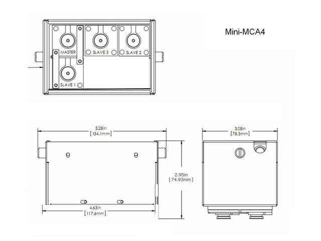
Dimensions (mm)
|
|
Mini-MCA4:
131.4 x 78.3 x 87.6
Mini-MCA6: 131.4 x 78.3 x 87.6
Mini-MCA12: 154.4 x 78.3 x 87.6
|
|
|
|
| |
Environmental
Note: the camera will
operate outside of the recommended environmental range, however
performance may be degraded.
|
|
-
Temperature
0 degrees Celsius to 40 degrees Celsius (32 degrees Fahrenheit to 104
degrees Fahrenheit)
-
Humidity
Less than 85% relative humidity,
non-condensing
|
|
|
|
| |
|
|
|
|
|
|
|
|
| |
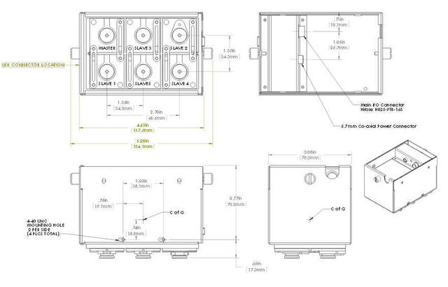
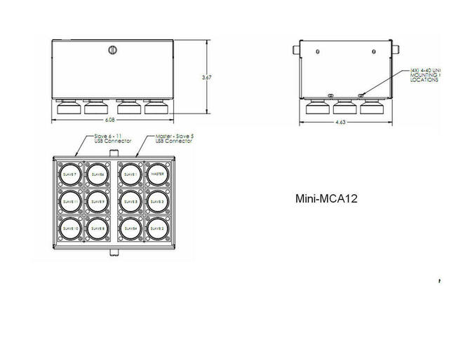
Additional
Mini-MCA Reference Information
Mechanical
Drawings and Photos
|
|
| |
|
|
| |
|
|
|
|
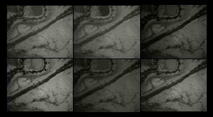
Low Resolution Examples of Mini-MCA6
Terrain Images (see Gallery for Originals)
|
|
|
|
|

|
|
|