| |
Overview
The ADC Snap and its accompanying software,
PixelWrench2, are ideally suited for high-speed capture of multi-spectral
images of crops, forests and other eco-systems.
Featuring 16 GB standard storage, fast parallel processing, ultra-low power consumption, and simple
menu-organized configuration and control, the ADC Snap captures visible light wavelengths longer
than 520 nm and near-infrared wavelengths up to 920 nm.
The ADC
Snap's exposure time is so fast that engineers in
our labs use this camera to capture stop-action
photos of fan blades on their desks. These stop
action cameras operate at speeds comparable to
industrial machine vision cameras.
Three filters atop the sensor limit the radiation that
enters it to bands of green, red and near-infrared
radiation equivalent to Landsat Thematic Mapper bands TM2, TM3 and TM4.
These bands are the basis for the standard "false color" composite images that
have become associated with multi-spectral imagery. They provide
excellent early warning signs of plant stress and their use as indicators of
other specific plant and soil conditions has been documented by scientists for
decades.
The ADC Snap
is housed in the same package as the ADC Micro. It
has the same weight, power consumption and interface
connections as the ADC Micro (see detailed specifications
below).
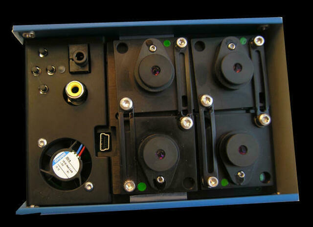
Sensors and Filters
The ADC Snap's principal difference
from the ADC Micro is that it uses a 1.3 MPel electronic
global snap sensor that creates images consisting of
1280 x 1024 pixels. Rather
than using a 'Rolling Shutter" sensor like ADC Micro
systems than scan each image from top to bottom, Micro-MCA
Snap system sensors expose the entire image at the same instant in
time. This allows ADC Snap images to be captured free of motion blur and
other distortions. The ADC
Snap camera is ideal for use with fast or low-flying
UAVs, especially fixed wing aircraft susceptible to
pitch, roll or yawing problems.
Image
Memory
The ADC Snap's 16 GB micro SD memory card is easily accessible by the user.
Images are stored along with
metadata such as GPS coordinates and/or attitude information (pitch,
roll and yaw) that is sent to the system through the ADC Snap's serial
interface (see I/O connections described below). Metadata
helps users establish the ground location of each image. After missions are completed, users remove the Micro SD memory
from the camera and transfer its contents to a host computer equipped
with PixelWrench2, the software included with all Tetracam
systems.
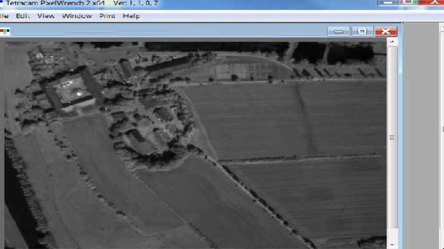
PixelWrench2
PixelWrench2 provides color processing of Tetracam RAW and DCM files,
complex batch processing tools, a comprehensive suite of image editing
tools and the ability to extract various vegetation indices such as
NDVI from the captured images.
In addition to indicating plant stress,
vegetation indices such as NDVI enable users to
deduce information such as
biomass, chlorophyll concentration in leaves, plant productivity
and fractional vegetation cover as well as predict crop yield. Refer to
System
Application Notes for descriptions of
example applications. |
|
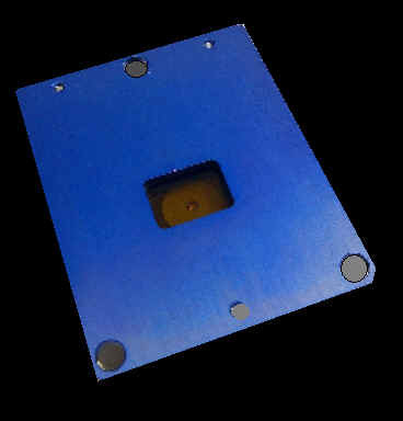
On the underside of the camera, the ADC
Snap possesses a high-quality 8.43 mm lens.
The lens focuses the light
that enters the camera on to the system's multi-spectral Snap Shutter image
sensor.
 |
|
| |
ADC Snap Sensor
Spectral
Response
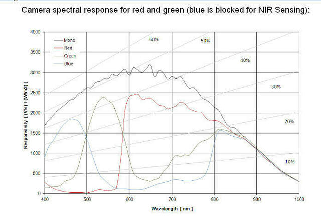
The graph above shows the
response of the sensor to different bands of light through the
red, green and blue filters. A blue absorbing glass filter is used
to eliminate the blue sensitivity, and the blue pixels in the
sensor are used to measure NIR. The image is then processed in
PixelWrench2 to subtract the measured NIR from the blue and red
bands to produce the final NIR/red/green image.
ADC Snap (with 8.43 mm Lens)
Ground Resolution & FOV Examples The
ADC Snap enables users to gather information about vegetation at
wavelengths traditionally monitored by satellites. Only,
flying in manned or unmanned aircraft, data gathered by the ADC
Snap is captured at times completely determined by the user,
independent of satellite latency, un-obscured by cloud cover and
in images that show considerably higher detail than images
captured from space (i.e., with resolutions measured in millimeters
per pixel rather than meters per pixel).
The
ADC Snap's field of view (FOV) is laid out in a 4:3 format. The
horizontal angle of view for the system is 37.67 degrees. The
vertical angle of view is 28.75 degrees. When carried in a manned or
unmanned aircraft, the field of view increases as the above ground
level (AGL) altitude increases.
As the AGL increases,
the camera's ability to resolve individual details on the ground decreases.
With its standard 8.43 mm lens, when flown at altitude of 400 feet (122
meters) above
ground level, this camera creates an image large enough to capture an area
measuring 95 meters wide by 71 meters high at a resolution of less than three inches
(72.36 mm) per pixel in a single shot.
Below is a table that
shows the ground resolution and field of view for images gathered at various
altitudes above ground. PixelWrench2 contains an FOV Optical Calculator
that enables determination of the system's field of view and ground resolution
for any user-specified altitude. For operation in the field, this
utility is also available as a free app that runs on Android cell phones.
For information on this app, click
here.
| Sensor & Lens Parameters |
Object Distance
(Altitude Above Ground Level in meters)
|
Ground Resolution
in mm per pixel |
FOV
(width x height)
in meters |
The
values shown at right were derived from the FOV (Field of View) Optical
Calculator contained in Tetracam's PixelWrench2 software (included with
this camera) using the current values for this camera shown
below:
Sensor Dimensions (mm): 6.59 x 4.9
Pixel Size (in microns): 5.0
Camera Lens Focal Length (mm): 8.43 |
122 m (~ 400 ft) |
72.36 |
95.4 x 70.9 |
213.4 m (~ 700 ft) |
126.54 |
166.782 x 124.517 |
365.8 m (~ 1200 ft) |
216.91 |
285.89 x 213.441 |
915 m (~ 3000 ft) |
542.58 |
715.115 x 533.895 |
Note: In order to view a larger
composite image of an area of interest, users may purchase third party
software that stitches multi-spectral images of adjacent areas captured by a
Tetracam system together into a larger image mosaic. For information on
such software, please send us
email.
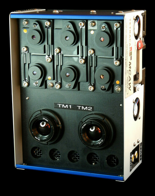
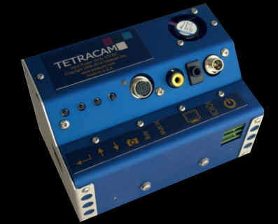
System Controls, Indicators and Connections
ADC Snap
Interconnection Pins
The ADC Snap
contains labeled interconnection pins at the top of
the front panel. These connect to the Un-terminated System Integration Cable
and to the ADC Snap Test and Control Box Assembly
and Cable, both of which are supplied with the
system. The Un-terminated System Integration Cable
may be used to connect the camera to external
devices in a manned or unmanned aircraft such as an
autopilot, GPS or video transmitter.
Information on the ADC Snap's flat Multi-IO
connector and the cables that are available from
Tetracam to connect to it are shown on our web site here.
| |
 |
|
Pin 15 GND: System Ground
Pin 14 +3VOUT: +3.3 Volts accessory power
Pin 13 VIDGND: Video ground reference
Pin 12 VIDEO:
NTSC or PAL Video signal out. The video format
is controlled by the SETTINGS.TXT file. Video
coax cables should be used for connecting video
devices.
Pin 11 SPARE: Unused input.
Pin 10 GRNLED: READY
Pin 9 REDLED: BUSY
Pin 8 RS232RX: (GPS IN)
Pin 7 RS232TX: Serial Output
Pin 6 SYNC: GPS Sync event input pin
Pin 5 SHUTTER: Ground to
take a picture
Pin 4 DOWN: Zoom live view to 1:1
Pin 3 UP: Un-implemented Menu Control Pin
Pin 2 SELECT: Un-implemented Menu Control Pin
Pin 1 +VDC: +5 Volt to +15 Volt input power pin
|
|
|
|
ADC Snap
Controls & Indicators
User control of the
ADC Snap is accomplished through hierarchical
system menus such as the one shown below. The system
menus present users with a series of configuration
choices. Scrolling through and selecting these
configures the camera.
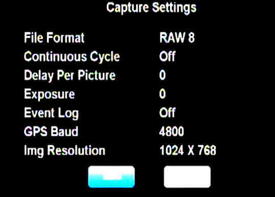
The system
menus are visible via a video display (supplied by the
user) interconnected by the ADC Snap Test and
Control Box Assembly
described below.
The Menus may be navigated by means of buttons visible on the top of the camera.
Viewed left to right, these allow you to scroll up, down or choose a
specific menu selection. An additional button
on the far right side of the panel allows you take a picture.
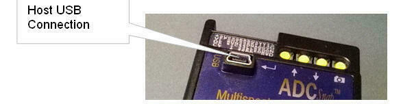
To the left
of these buttons, the ADC Snap contains a USB
connector. System
menus may be accessed via the system software
(PixelWrench2) running on a Windows computer
connected to the ADC through its USB interface.
Check out
the ADC Snap
User Manual for
precise descriptions of the system menus.
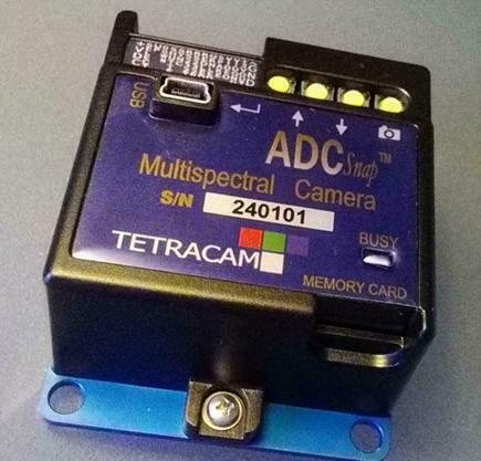
The ADC Snap
contains a Busy indicator on the top of the camera.
The indicator is lit red when the camera is busy
processing a captured image. The indicator is
lit green when the camera is ready to capture a new
image.
The
system's Micro SD Card is inserted at the bottom of
the camera's face panel. The card is removed from
the ADC Snap in order to transfer images to a
computer for processing. This card may be inserted
directly into a computer that will accept such cards
or it may be connected to a computer through a Micro
SD/USB adapter provided with the camera.
ADC Snap Cable
The cable
provided with the ADC Micro is
an
un-terminated System Integration Cable. This
has the same pin-outs as are present on the ADC
Micro edge connector. The un-terminated cable enables the user
to connect the camera to
other equipment in a manned or unmanned aircraft
(e.g., autopilot, GPS system or video transmitter). |
|
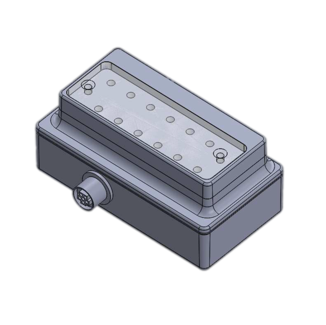
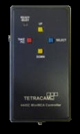
Test and
Control Box Assembly
The ADC Snap
Test and Control Box Assembly (shown at right) is included with each
ADC Snap system.
This contains buttons that enable the user to
manually scroll up and down through system menus,
pick a selection or take a picture. Via its 15-Pin
Multi-I/O connector, this box also may be used to
interconnect the camera with the RS232 transmit
and receive lines of an optional GPS receiver in
order to determine GPS coordinates at image capture
time. The box may also be used to interconnect the
camera's NTSC or PAL video signal output to an
external monitor. |
 |
Camera Triggering Options
The ADC Snap may
be triggered by various means depending upon the user's
preference. These include:
-
On-Camera Shutter Release: The
ADC Snap possesses a Take Pic button on the camera itself which when pressed triggers the camera
-
Auto-Timer: The ADC Snap may be configured to capture images continuously at intervals
specified by the user via the camera's system menus.
Press the Shutter Release or trigger the system via one of the methods
below to begin continuously capturing images. Press the Shutter
Release or trigger the camera again to stop continuous capture of images.
Always stop continuously capturing images by pressing the On-Camera
Shutter Release or via a trigger command prior to powering the system off.
Interruption of power during continuous capture of images may damage the
ADC Snap.
-
Remote Shutter Release: The
ADC Snap's included Controller Box enables users to manually trigger the
camera by pushing a button at the desired moment.
-
External Triggering on UAV: Used on a UAV, UAV
circuitry may be patched through its un-terminated System Integration
Cable (included with the system) to deliver a low-true TAKE PIC command to the
ADC Snap via Pin 5.
-
RS-232
Triggering: The camera may be commanded to trigger by receiving
an <ESC> T command via the RS232 connection on the ADC/MCA
Box. Due to the delays incumbent in a serial interface, the RS232
link is more commonly used to transfer GPS position coordinates to the
camera at camera trigger time. When the camera is connected to a GPS
receiver via its System Integration Cable, the camera records the
coordinates of the location at which each image is captured into its
log file upon receiving any camera trigger command.
|
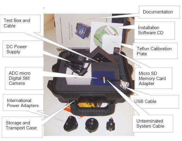
Standard System Contents
|
System Contents Includes:
-
ADC Snap Agricultural Digital Camera
-
CDROM with Installation Software and
Documentation
-
Product Manual and Accessory Documentation
-
USB Interconnection Cable
-
16 GB Micro SD memory card
-
Micro SD to USB Reader/Adapter
-
DC Power Supply with International
Adapters
-
White Teflon Calibration Plate (AKA
Calibration tag or Software Calibration Tile)
-
Test and control box assembly and Cable
-
Un-terminated System Integration Cable
-
Hardened Plastic Storage and Transport
Case
Typical Availability:
2 to 3 weeks (although faster turnaround times are
often
possible). Please contact us for more information regarding
configuration options, pricing and availability.
Options Commonly Purchased with this Product:
|
System Contents:
 |
|
|
| |
|
Summary of ADC Snap System Features and Specifications
|
|
Specification/Feature |
|
Description/Value |
|
Remarks
|
|
|
|
System Overview |
|
90 gram 1.3 MPel
Multispectral
R-G-NIR System principally
designed for operation aboard unmanned aircraft
|
|
The ADC Snap, ADC Micro and ADC Lite are
specifically designed for operation aboard unmanned aerial vehicles.
The advantage of the ADC Snap is that its faster image capture
time optimizes this camera for high-speed flight close to the
ground or for use with UAV systems that are prone to yawing,
pitching or rolling. |
|
|
|
Multispectral Bands |
|
3-Fixed Green, Red, NIR (Equivalent to Landsat TM2,
TM3, TM4)
|
|
|
|
|
|
Indicators
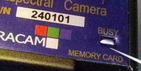 |
|
The ADC Snap Busy LED is
located on the lower right side of the front of the camera.
Red indicates a Busy
condition. Green, a Not Busy condition. When this
indicator is lit green, the camera is ready to capture a new
image.
|
|
The
ADC Snap Busy LED glows red at the exact beginning of
integration of an image into the camera's sensor. The
indicator stays red until the image is saved in memory. During this
time, the camera is not able to capture another image. When
this LED is green, the camera is not busy and another image
may be captured.
|
|
|
|
Memory |
|
16 GB Micro SD Memory
Card provided standard with equipment |
|
In order to run at the
fastest image cycle time we recommend use of 16GB Sandisk
Extreme Plus or Extreme Pro Class 10/UHS-1 Micro SD memory
cards. Camera cycle time with these cards should be less
than 1 second in the raw 10 bit RWS10 format.
|
|
|
|
Default Ports |
|
Video (NTSC or Pal), USB,
RS232 Serial, Remote Shutter (External Trigger)
|
|
|
|
|
|
Video (NTSC or PAL) |
|
Used to view system
menus for system configuration or to act as camera viewfinder.
The video format and viewing mode (system menus or viewfinder)
are user selectable. |
|
Video is accessible through
the ADC Snap's Interconnection Pins 12 and 13. These
pins may be connected to the Test and Control Box Assembly
which contains an RCA video connector or they can be wired to
a monitor or video transmitter via an included Un-terminated
System Integration Cable. |
|
|
|
USB |
|
USB 2.0 used to connect the
camera to a computer for system configuration
|
|
The
USB 2.0 connection for the camera is located on top of the
housing as shown in the illustration below. For reliable USB
2.0 communications, good quality USB 2.0 rated cables should
be used that are less than 2 meters in length. The camera uses
too much initial power to be supplied directly from the USB
cable. It must have an external power supply attached prior to
being plugged in for enumeration.
The
camera always operates as a USB Disk device when attached to a
host. The camera will be recognized by its volume ID
TTCDISKS when the Pixelwrench2 GPS Distiller application is
started. Files can be dragged and dropped to and from the
camera from any personal computer that has USB disk drivers.
|
|
|
|
RS232 Serial |
|
Principally used to
connect to devices that stream continuous GP coordinates or
other location information in standard NMEA sentences to the
camera through its Interconnection Pins 7 and 8. These
pins may be connected to the Test and Control Box Assembly
for connection via a 3.5mm stereo phone plug to an external
device or wired directly to the external device via an
included Un-terminated System Integration Cable. |
|
By default, the camera
serial port is configured 4800, the NMEA 0183
standard configuration. Serial configuration may be
altered via system menus. GPS coordinates and other data
is saved in the camera's image memory as metadata. This
may be extracted by PixelWrench2 or other application
software. The serial port may also be used to control
the camera from an external serial interface using simple text
commands (see User Manual for details). |
|
|
|
Remote Shutter |
|
Used as an external
trigger to initiate image capture through the ADC Snap's
Interconnection Pin 5. |
|
Images are triggered by
grounding pin 5. |
|
|
|
|
|
|
|
|
|
|
|
Power |
|
+
9.0 VDC
to + 14.7 VDC (160 mA);
Two watts nominal |
|
|
|
|
|
|
|
|
|
|
|
|
|
ADC Snap Sensor |
|
|
|
|
|
|
|
Range |
|
520nm
to 920nm |
|
520nm
to 920nm |
|
|
|
Size in Pixels |
|
1.3 MPel |
|
1280 x 1024 pixels |
|
|
|
Dimensions |
|
6.59 mm x 4.9 mm |
|
|
|
|
|
Pixel Size |
|
5.0 microns
|
|
|
|
|
|
Optics |
|
|
|
|
|
|
|
Focal Length |
|
8.43 mm fixed lens |
|
|
|
|
|
Aperture |
|
f/3.2 |
|
|
|
|
|
|
|
|
|
|
|
|
|
Horizontal Angle of View |
|
37.67 degrees |
|
Consult FOV calculator in
PixelWrench2 - See also
FOV Android APP |
|
|
|
Vertical Angle of View |
|
28.75 degrees |
|
Consult FOV calculator in
PixelWrench2 - See also
FOV Android APP |
|
|
|
Default
Depth of Field |
|
~3 m to infinity |
|
Consult FOV calculator in
PixelWrench2 - See also
FOV Android APP |
|
|
|
Image
Exposure time |
|
Auto or menu-selectable in
ms |
|
|
|
|
|
Image
Triggering |
|
On-Camera Shutter Release,
Auto-Timer, Remote Shutter (External Trigger), RS232 Serial Trigger |
|
|
|
|
|
Default Image Dimensions |
|
1.3 Megapixel (1280 x 1024 pixels) |
|
ADC Snap image size may be adjusted to an alternate image size
via system menu selection
|
|
|
|
Default Image Storage Medium
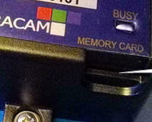 |
|
The ADC Snap stores all
images and metadata on a standard 16 GB Micro SD memory card
which is inserted into the camera in the Memory Card slot
beneath the Busy Indicator. |
|
The Micro SD card may be
inserted directly into a computer that will accept such cards
or it may be connected to a computer through a Micro SD/USB
adapter provided with the camera. |
|
|
|
Default Image File Types |
|
.RWS is
the snap shutter version of the .RAW files saved be other
cameras. After removal of noise and pixel reordering, these
are converted to .RAW images.
.DCS
is a snap shutter variant of the .DCM compressed format.
|
|
The shifting scheme of the sensor and
the fact that these sensors are susceptible to high dark
current noise require correcting these problems during
post-processing on the host computer. Consequently, the
images taken by the ADC Snap camera have different file
extensions than those of the rest of the ADC family to enable
PixelWrench2 to recognize that special post-processing
correction to these images will be necessary.
Once
processed, image file formats are translatable via
PixelWrench2 into other common image file types such as BMP, JPEG,
TIFF, PNG, etc.
Images initially appear as monochrome
images. PixelWrench2's Index Tools enable users to translate
monochrome images to false color images and then derive
vegetation indices such as NDVI from these.
The RWS files are quite
large: 2.6 megabytes for the 10 bit format and 1.3 megabytes
for the 8 bit format. Compression (DCS format) cuts the size
of the files in half and retains full precision, but takes
longer to capture. The DCS compressed continuous mode may be
designated as low speed. Besides the smaller file size,
another advantage of the DCS format is that the files contain
previews which speed up the image access speed using
Pixelwrench2.
 |
|
|
|
Typical Number of Images Captured
Per Mission |
|
Approximately 5000 + images
depending upon selected file type (i.e., 10 bit DCM lossless,
8 bit RAW, and 10 bit RAW file types). |
|
Higher numbers of images
may be captured per mission by substituting an optional larger
Micro SD Card for the 16 GB card included in the camera's
standard contents. |
|
|
|
Image
Capture Interval
(Speed dependent on SD Card
Features) |
|
Capacity:
(DCS10) Approx.1.8MB per
image
(RWS10)2.6MB per image
(RWS8) 1.3 MB per image
Rate:
(DCS10) Capture to
end of cycle: ~ 3 sec.
(RWS10) Capture to ready
: 1.0 sec.
(RWS 8) Capture to
ready : 1.2 sec.
|
|
The
highest rate of capture is with the 10 Bit RWS file format, at
about one picture per every second, depending on the speed of
the micro SD memory card. For users who want more pictures on
a card, and do not need precision, the 8 bit RWS format is the
next fastest, about 2.5 to 3.5 seconds per picture.
The
camera can capture still images at reduced resolution to speed
up the camera cycle time. Choose 1280 X 1024 for full
resolution shots and 1+ second cycle time. Choose 640 X 512
for half resolution and .5 second cycle time.
|
|
|
|
Included Software |
|
PixelWrench2 is included
with each purchase of an ADC Snap |
|
PixelWrench2 enables users
to convert images captured in Tetracam native file formats to
file types commonly used with other software. The
software also enables users to convert the green, red and
invisible NIR bands captured by the camera as a monochrome
image into blue, green and red respectively for presentation
in false color images and, following this, extraction of vegetation
indices such as NDVI from these. See
PixelWrench Product Web Page and the Help menu in
the software for further details. |
|
|
|
Weight |
|
90 g (3.17 ounces) |
|
|
|
|
|
Dimensions |
|
75 mm x 59 mm x 33 mm
2.97" x 2.33" x 1.29" |
|
|
|
|
|
Environmental
Note:
the camera will operate outside of the recommended
environmental range, however performance may be degraded.
|
|
-
Temperature
0 degrees Celsius to 40 degrees Celsius (32 degrees
Fahrenheit to 104 degrees Fahrenheit)
-
Humidity
Less than 85% relative humidity, non-condensing
|
|
|
|
|
|
|
|
|
|
|
|
|
|